YoungMakersYourduinoDetail1
DETAIL ABOUT PIN 13, LED, RESISTOR
Here is the YourDuino RoboRED Microcomputer (Arduino UNO Compatible)
Let's look in DETAIL at the built-in LED that you can control with MIXLY or the Arduino IDE.

Here we are looking at the actual physical and electronics reality:

WATCH CLOSELY NOW!
- * Find the actual LED that lights up when you set pin 13 HIGH (Just to left of label)
- * Find the actual RESISTOR on the diagram (Just to left of label)
These are very small "surface Mount" components that are soldered (with melted lead) to copper traces that are on the circuit board.
- MORE CLOSELY:
- * Read the resistor VALUE. (Upside Down!) 102 Means One-Zero-and two zeros: 1 0 00 or 1000 Ohms. Details!
- *
CIRCUIT TRACING

Now let's look VERY closely at the circuit board of the RoboRED:
There are many small copper lines (traces) that are the "wiring" of the circuit board. The copper is coated with red lacquer to protect it. But if we look closely we can see the traces.
Note the white dots we added to the trace we are interested in.
The copper wiring trace goes from the pin on the ATMEL 328 CHIP (that is what you program) straight up to:
- A junction to the left, over to the RESISTOR.
- Then straight up, then 90 degree left turn, then 45 degree up turn...
- All the way up to the leftmost yellow pin. THAT is where you will connect a wire from "Pin 13" to some other part.
There are hundreds of traces like this that do all the "wiring" on the RoboRED.
How is the 328 CHIP Wired??
Oh, you thought THOSE traces were small ?? The chip inside that black square has more than 100,000 traces. And they are very, very small.
The Arduino board that you can hold in your hand has a "Chip" on it which is the actual computer you are programming. The chip is the square black thing above and right of the "RoboRED" label in the photo below. There are 32 silver colored metal connections around it, 8 on a side.
The black square is really plastic and it protects the actual CHIP which is inside it. WIKIPEDIA page of the Arduino CHIP (click)
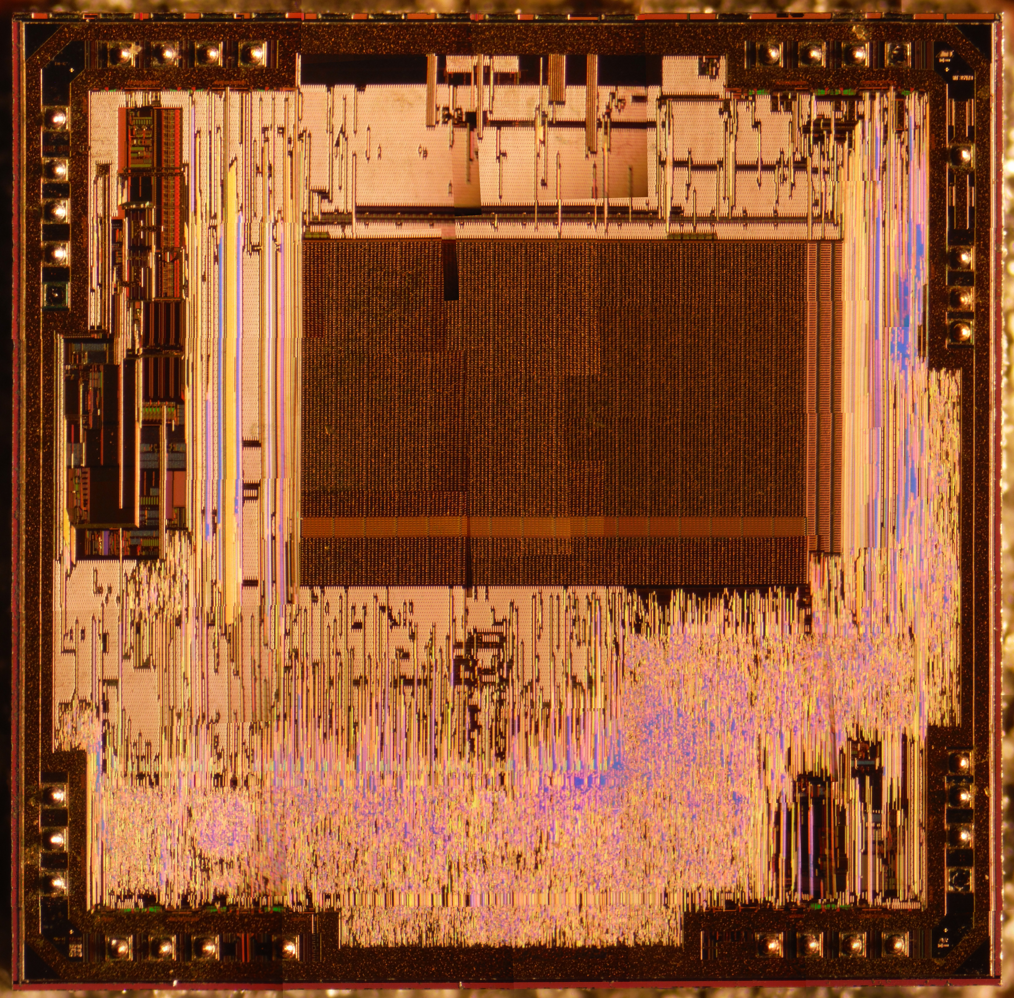
What a chip really looks like
If you used some (dangerous chemicals) to remove most of the plastic you could see the actual chip inside. It would look like this:

The connections from the silver colored outside pins to the chip are the tiny gold wires. An Arduino UNO chip in the factory, before being "encapsulated" in the plastic looks like this:

OH, you wanted the DETAILS?? Click HERE