YourSmartArduino
YourSmartArduino
NOTE: This kit is UNDER CONSTRUCTION although basically working... Comments, suggestions to terry@yourduino.com
It is a challenge to introduce the concepts of Physical Computing (WikiPedia) to younger students who have no previous experience with electronic devices, sensors, actuators and programming. For an explanation of Physical Computing from one of our existing kits,
(See THIS PAGE).
We hope to be collaborating with the CSforAll Consortium (http://www.csforall.org) in providing the curriculum materials and specific classroom materials for this effort. More details as we learn more.
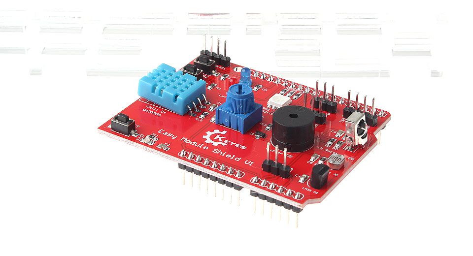
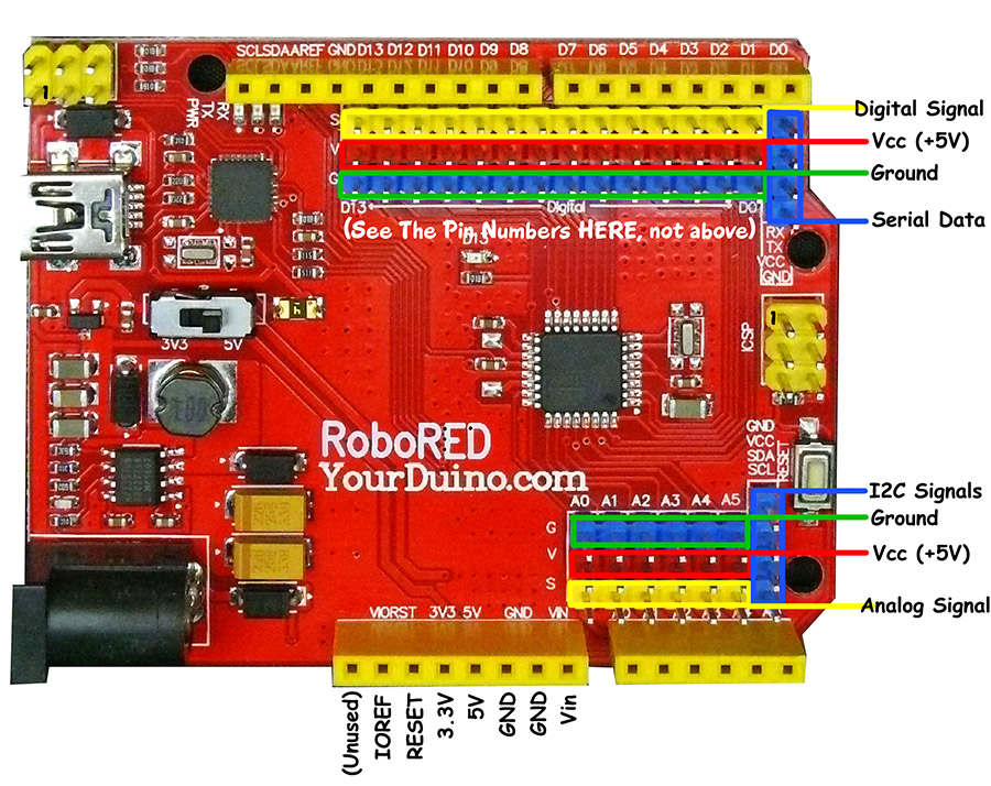
We are working on a Arduino Kit and accompanying Educational Materials that are specifically aimed at youngsters from approximately 8 to 12 years old, that begins with several "Lessons" using various sensors and actuators. The kits will have the Arduino (our UNO-compatible YourDuino RoboRED) pre-programmed with 8 to 10 Lessons as individually-selectable Software Sketches. The lessons are selected with an IR Remote. The kit will be able to run on a student's desk without an external computer, powered by a 9V 1 amp power supply or a battery case (supplied) with 6 AA batteries. It starts with a multipurpose shield (LEFT) plugged into the YourDuino RoboRED (RIGHT).


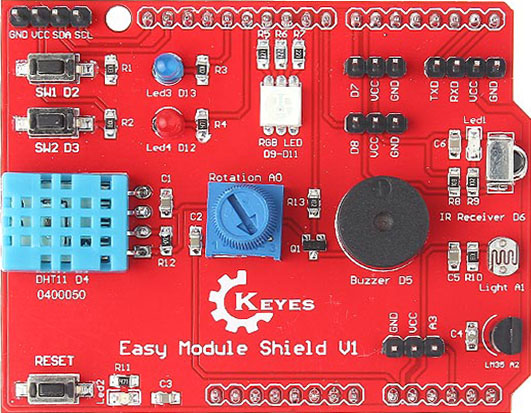
The shield (right) includes many sensors and actuators that the student will be able to use in becoming familiar with the concepts of Physical Computing plus functions and the appearance of electronic components. It includes these components:
- Two pushbutton switches
- Two LED module
- One Multicolor color RGB LED module
- Infrared receiving module (with handheld remote)
- Light sensor module
- Temperature and Humidity (DHT-11) sensor module
- Sound output tone module (labeled "Buzzer")
- Knob rotation potentiometer module
- DHT11 temperature and humidity sensor module
- I2C interface (can be used with external LCD display)
- TTL serial port
- Two general-purpose digital input-output ports (D7 and D8)
- A general-purpose analog port (A3)
The students can learn about and run many of the sensors and actuators on the shield without handling wires or writing code. This makes the classroom environment much easier to organize and manage in the beginning of a curriculum.
Other Devices - Plug-in cables:
The next level has the student attach external 3-pin cables to devices, to become familiar with different types of hardware:
- A large pushbutton and cable to learn about switches, conductors, insulators
- A bright white LED module connected to act as a strobe light for experiments.
- An LCD Display that can show Values such as Temperature, Humidity, Distance and others.
- A Servomotor that can be controlled by a knob on a potentiometer
- A "Buzzer" sound maker
- An Ultrasonic Distance Sensor
- A waterproof electronic Temperature Sensor with 1M cable and interface module
- A colorful knob potentiometer to control various experiments
- A variety of sensors that provide a simple ON-OFF response:
- Tilt switch
- Vibration sensor
- Motion Sensor (Human motion)
- Light Sensor (Later to be used in Analog mode)
- Sound Sensor (Later to be used in Analog mode)
- OTHER/UNDECIDED:
- Joystick
- Accelerometer
| Big Button Switch |
| BRIGHT! White LED |
| Servomotor |
| Buzzer |
| TemperatureSensor |
| Colorful Knob Potentiometer |
IR remote:
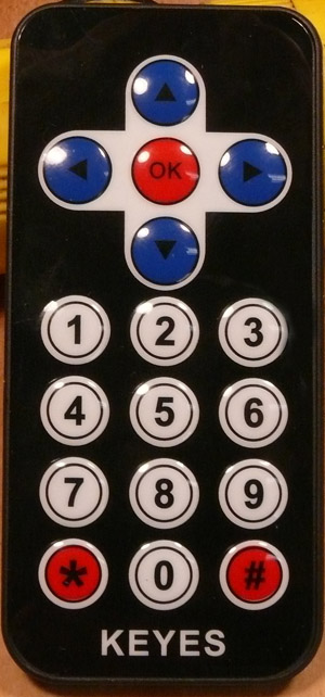
A handheld Infrared Remote (Left) will be used to select one of several pre-loaded Arduino programs (sketches).
  It will also be used to control some functions in later software.
LCD Display:external image thumb_170_LCD-1602-2.jpg
Students will use a plug-in cable to attach a small LCD display that can display values from sensors to understand the concepts behind devices such as pushbuttons, light sensor, temperature sensor, humidity sensor, and rotating knob position.
Breadboard:external image detail_168_breadboard-8cm-1-800.jpg
A breadboard will be used (still using pre-programmed system) to learn about making external connections and using devices that are not supplied with simple 3-pin cables. This is preparation for later learning to make individual projects. This will include these components:
- pushbuttons
- resistors
- LEDs ( 5 colors)
- Light sensor (PhotoResistor)
- Another type of Temperature sensor (Thermistor)
"Rainbow" Cable and 3-pin cables:{| class="captionBox" style="float: right" | class="captionedImage" | 3-pin cable |- | class="imageCaption" | 3-pin cable |}{| class="captionBox" style="float: right" | class="captionedImage" | Rainbow Cable |- | class="imageCaption" | Rainbow Cable |}{| class="captionBox" style="float: right" | class="captionedImage" | Pin Strip |- | class="imageCaption" | Pin Strip |}
- 40-Jumper-Wire Rainbow cable 20 cm long, (Right, showing one end) that can be separated to make any width cable, and 1-wire jumpers
- "Pin Strip" to create male connections when necessary
- 3-pin cables (right) (Flat end to Latching End) to connect devices shown above
- 3-pin cables (Flat end to Separate End) to connect devices shown above and other components
- 4-pin cable that plugs from LCD Display to RoboRED I2C connectorexternal image detail_409_6AA-2x3.jpg
Battery case for 6 AA batteries (with Arduino plug) (Right)
NOTE: A printed How-To manual will be needed by students to use this kit without an external computer.
NOTE: Hardware and preloaded Arduino code for this section is under development (3/17).
Using the SmartDuino kit with an external computer
After the previous level of learning, the Arduino (YourDuino RoboRED) and sensors / actuators can be used WITH a computer to start to learn Arduino programming.
Drag-Drop Programming:
A drag-and-drop (SCRATCH-Like) programming environment (ArduBlock or Mblock) can be used as a transition from the pre-programmed environment to a Student-programmed system using the well-developed Arduino Integrated Development Environment (IDE). ArduBlock can display the actual Arduino code created by an ArduBlock sketch. This provides a transition from the drag-drop environment to sequential, procedural Code.
Conventional Coding Environment:
At this level, student involvement approaches the complexity provided by the existing kits used by many high schools and universities. A student uses the Arduino Integrated Development Environment (IDE) and writes code that is uploaded to the Arduino and replaces the previous pre-loaded code. (The pre-load code is available for reload too). Example excerpts of the materials used at this level are here:
MakerSpace Engineering Kit: Learning about many different Sensors and Actuators and coding to utilize them
Basic Robot Kit: Learning about Physical Computing, motor control, robot control, collision avoidance etc.
CODE behind the Pre-Loaded lessons:
EARLY example of the underlying code approach for providing a number of pre-loaded independent Lesson-supporting "Sketches" :
(This version uses about 1/3 of the Arduino memory):
Sketch uses 10,980 bytes (34%) of program storage space. Maximum is 32,256 bytes.
Global variables use 741 bytes (36%) of dynamic memory, leaving 1,307 bytes for local variables. Maximum is 2,048 bytes.
/* YourSmartDuino-EM
  - WHAT IT DOES: Provides several preprogrammed options for users
  - Uses the KEYES Easy Module Shield V1
  - SEE the comments after "//" on each line below
  - CONNECTIONS: KEYES Easy Module Shield V1
  D2  Pushbutton SW1
  D3  Pushbutton SW2
  D4  DHT11 Temperature/Humidity Sensor
  D5  Buzzer (Really a beeper)
  D6  IR Receiver
  D7  3-pin D7
  D8  3-pin D8
  D9  RGB LED
  D10 RGB LED
  D11 RGB LED
  D12 LED4 (RED)
  D13 LED3 (BLUE)

  A0  Rotation (10K Pot)
  A1  Light (Photoresistor)
  A2  LM35  (Temperature Sensor)
  A3  A3 (3-Pin)
  A4  SDA
  A5  SCL
   -
   -
  - V1.36 03-15-2017    IR Remote  TimerFreeTone
   Questions: terry@yourduino.com */

/*-----( Import needed libraries )-----*/
#include "IRremote.h"
#include <OneWire.h>
#include <DallasTemperature.h>
#include <LedFlasher.h>   // From Nick Gammon
#include<ButtonV2.h>
#include <TimerFreeTone.h>
#include "pitches.h"      // for Tone library


/*-----( Declare Constants and Pin Numbers )-----*/
// NOTE: PWM Pins = 3,5,6,9,10,11
#define OPTION_SEL_1_PIN  2    // Option Select pins
#define OPTION_SEL_2_PIN  3   // Pins select options 0..7

#define SWITCH1_PIN       2
#define SWITCH2_PIN       3
#define DHT11_PIN         4
#define BUZZER_PIN        5   // This is really a tone beeper

#define IR_RECEIVER_PIN   6
#define D7_PIN            7
#define STROBE_LED_PIN    7
#define ONEWIRE_PIN       7
#define D8_PIN            8
#define SERVO_PIN         8

#define RGB_RD_PIN        9   // PWM disabled by servo
#define RGB_GN_PIN        10
#define RGB_BL_PIN        11

#define DIMMABLE_LED_PIN  9

#define RED_LED_PIN       12     // "LED2 Red"
#define ONBOARD_LED_PIN   13     // "LED3 Blue"

#define ROTATION_PIN       A0    // Analog inputs from Potentiometer etc.
#define LIGHT_SENSOR_PIN   A1    // Photoresistor
#define TEMPERATURE_SENSOR A2    // LM35
#define A3_PIN             A3    // 3-pin connector
#define I2C_SDA_PIN        A4    // I2C Interface OR Joystick
#define I2C_SCL_PIN        A5

// NOTE: Pins A4 and A5 are used for I2C communication to LCD Display

#define ForEver  TRUE       // For use in looping

#define ServoMIN  20  // Don't go to very end of servo travel
#define ServoMAX  160 // which may not be all the way from 0 to 180.

/*-----( Declare objects )-----*/
IRrecv irrecv(IR_RECEIVER_PIN);       // create instance of 'irrecv'
decode_results results;               // create instance of 'decode_results'
/* Set up a oneWire instance to communicate with any OneWire device*/
OneWire ourWire(ONEWIRE_PIN);

/* Tell Dallas Temperature Library to use oneWire Library */
DallasTemperature sensors(&ourWire);

int Led13OnTime  = 100;
int Led13OffTime = 900;
LedFlasher LED13 (ONBOARD_LED_PIN, Led13OffTime, Led13OnTime);   // OffTime, OnTime

ButtonV2 BlueButton;

/*-----( Declare Variables )-----*/

int   OptionNumber;     // Option as defined by the pin selects
int   AnalogInputValue; // Analog values from 0..1023

unsigned long     StrobeLastMs ;
unsigned long     StrobeLedOnTime  = 10L ;  // Variables for Strobe LED
unsigned long     StrobeLedOffTime = 1000L ;
boolean InStrobeTime = FALSE;
boolean StrobeIsOn   = FALSE;

int     ServoPosition ;

void setup()   /****** SETUP: RUNS ONCE ******/
{
  Serial.begin(115200);        // Start up the Serial Monitor
  Serial.println();
  Serial.println("Your Smart Duino STARTUP");
  irrecv.enableIRIn(); // Start the IR Remote receiver
  // NOTE: OneWire library sets pinMode for its pins

  pinMode(RGB_RD_PIN, OUTPUT);
  pinMode(RGB_GN_PIN, OUTPUT);
  pinMode(RGB_BL_PIN, OUTPUT);
  pinMode(STROBE_LED_PIN, OUTPUT);
  pinMode(ONBOARD_LED_PIN, OUTPUT);
  pinMode(SERVO_PIN, OUTPUT);
  pinMode(RED_LED_PIN, OUTPUT);
  pinMode(OPTION_SEL_1_PIN, INPUT_PULLUP);
  pinMode(OPTION_SEL_2_PIN, INPUT_PULLUP);

  BlueButton.SetStateAndTime(LOW);

}//--(end setup )---


void loop()   /****** LOOP: RUNS CONSTANTLY ******/
{
  switch (OptionNumber)
  {
    case 0:
      /*-------------( Option 0: Blinks Morse Code "HI" on pins 12 and 13. )---------------
         User sees blink on onboard LED pin 13.
         User connects buzzer brick to pin 13 so Morse is audible
         Morse is discussed. Digital is discussed. Look at cables and colors.
         User uses a cable to connect bright LED brick to pin 12
      */
      {
        Serial.println("Option 0");
        do
        {

//--------( Check if user has sent a IR Remote Command )------------------------------
          if (irrecv.decode(&results)) // have we received an IR signal?
          {
            translateIR();   // Translate the IR data, and change the Option Number
            irrecv.resume(); // receive the next value
          }
          BlinkHi();
        } while (OptionNumber == 0);  // Loop here "ForEver" or until a different option requested
        break;
      } // END case


    case 1:
      /*-------------( Option 1: User connects different switches to A3 )---------------
         User pushes button, ON-OFF, TRUE-FALSE, 1-0, HIGH-LOW discussed.
         Other bricks are connected to pin A3: Tilt, Vibration, Motion Detect, Light, Sound
         Bare wires connected to pin A3; conductors/insulators discussed.
         Bright LED reconnected to pin 12: BLINKS when switch is ON.
      */
      {
        Serial.println("Option 1");
        pinMode(A3,INPUT_PULLUP);

        do
        {
          if ((digitalRead(SWITCH1_PIN) == 0) or (digitalRead(A3) == 0))
          {
            digitalWrite(STROBE_LED_PIN, HIGH);
            delay(50);
          }
          else
          {
            digitalWrite(STROBE_LED_PIN, LOW);
          }
          LED13.update ();
        } while (ForEver);  // Loop here "ForEver" or RESET

      }// END case


    case 2:
      /*--------------( Option 2: Analog variable from user's Potentiometer controls" )----------------
         Dimming of Bright LED on Pin 11
         Strobe blink speed on Bright LED on Pin 12
         Servo Position on pin 3
      */
      {
        Serial.println("Option  2");
        do
        {
          AnalogInputValue = analogRead(ROTATION_PIN);   // Read the position of the Potentiometer
          //         Serial.print("Analog Value = ");
          //         Serial.println(AnalogInputValue);
          analogWrite(DIMMABLE_LED_PIN, AnalogInputValue / 4);

          /*-----------( Set up and control strobe frequency and duration )-----------------------------*/
          StrobeLedOffTime = (1023 - AnalogInputValue) / 2L;  // Set Strobe parameters from Analog Input
          StrobeLedOnTime  = StrobeLedOffTime / 10L;

          if (InStrobeTime)
          {
            if
            (
              ((StrobeLastMs + StrobeLedOnTime) < millis())
              &&
              StrobeIsOn
            )
            {
              StrobeIsOn = FALSE;
              digitalWrite(STROBE_LED_PIN, LOW);
            }

            if
            (
              ((StrobeLastMs + StrobeLedOnTime + StrobeLedOffTime) < millis())
              &&
              ! StrobeIsOn
            )
            {
              InStrobeTime = FALSE;
            }


          } // END InStrobeTime

          else // Begin another Strobe cycle
          {
            StrobeLastMs = millis();
            InStrobeTime = TRUE;
            digitalWrite(STROBE_LED_PIN, HIGH);
            StrobeIsOn   = TRUE;

          }

          /*-----------( Set Servo position from Potentiometer value and Send Servo Position to Servo )--------------------*/

          ServoPosition  = map((1023 - AnalogInputValue), 0, 1023, 900 , 2000);
          PointServo(ServoPosition);

          LED13.update ();
        } while (ForEver);  // Loop here "ForEver" or RESET
      } // END case

    case 3:
      {
        Serial.println("Option 3");
        do
        {

          byte type = BlueButton.CheckButton(SWITCH1_PIN); // current time and length of time to press the button as many times as you can ie. 1.5 seconds
          switch (type)
          {
            case WAITING:
              break;
            case PRESSED:
              Serial.println("pressed 1 time");
              break;
            case DOUBLE_PRESSED:
              Serial.println("pressed 2 times");
              break;
            case MULTI_PRESSED:
              Serial.println("pressed 3 times");
              break;
            case HELD:
              Serial.println("Button HELD");
              break;
          }
          LED13.update ();
        } while (ForEver);  // Loop here "ForEver" or RESET
      } // END case

    case 4:
      {
        Serial.println("Option 4");
        do
        {
          BlinkHi();
          delay(2000);
        } while (ForEver);  // Loop here "ForEver" or RESET


      } // END case

  } // End switch

}//--(end main loop )---

/*-----( Declare User-written Functions )-----*/

void BlinkHi()
{
  int i;
  for (i = 0; i < 4; i++)
  {
    digitalWrite(ONBOARD_LED_PIN, HIGH);   // turn the ONBOARD_LED_PIN on (HIGH is the voltage level)

    // Check if the user has pressed buttons
    if (digitalRead(SWITCH2_PIN) == LOW) {
      digitalWrite(STROBE_LED_PIN, HIGH);  // turn the STROBE_LED_PIN on (HIGH is the voltage level)
    }
    if (digitalRead(SWITCH1_PIN) == LOW) {
      TimerFreeTone(BUZZER_PIN, 800, 100);
    }

    delay(100);               // wait for 1/10 second
    digitalWrite(ONBOARD_LED_PIN, LOW);    // turn the LED off by making the voltage LOW
    digitalWrite(STROBE_LED_PIN, LOW);     // turn the LED off by making the voltage LOW
    delay(200);               // wait for a second, watch the Dark
  }
  delay(200);
  for (i = 0; i < 2; i++)
  {
    digitalWrite(ONBOARD_LED_PIN, HIGH);   // turn the LED on (HIGH is the voltage level)

    // Check if the user has pressed buttons
    if (digitalRead(SWITCH2_PIN) == LOW) {
      digitalWrite(STROBE_LED_PIN, HIGH);  // turn the STROBE_LED_PIN on (HIGH is the voltage level)
    }
    if (digitalRead(SWITCH1_PIN) == LOW) {
      TimerFreeTone(BUZZER_PIN, 800, 100);
    }

    delay(100);               // wait for 1/10 second
    digitalWrite(ONBOARD_LED_PIN, LOW);    // turn the LED off by making the voltage LOW
    digitalWrite(STROBE_LED_PIN, LOW);     // turn the LED off by making the voltage LOW
    delay(200);               // wait for a second, watch the Dark
  }
  delay(1000);
}

boolean IsTime(unsigned long *timeMark, unsigned long timeInterval)
{
  if (millis() - *timeMark >= timeInterval) {
    *timeMark = millis();
    return true;
  }
  return false;
}


void PointServo(int ServoAngle)
{

  for (int i = 0; i < 3; i++) // Send the pulse 10 times
  {
    digitalWrite(SERVO_PIN, HIGH);
    delayMicroseconds(ServoAngle);
    digitalWrite(SERVO_PIN, LOW);
    delay(1);
  }
}// PointServo end
/*---------------------------*/


void translateIR() // takes action based on IR code received

// describing KEYES Remote IR codes

{

  switch (results.value)

  {

    case 0xFF629D: {
        Serial.println(" FORWARD");
      } break;
    case 0xFF22DD: Serial.println(" LEFT");    break;
    case 0xFF02FD: Serial.println(" -OK-");    break;
    case 0xFFC23D: Serial.println(" RIGHT");   break;
    case 0xFFA857: Serial.println(" REVERSE"); break;
    case 0xFF6897: {
        Serial.println(" 1");
        OptionNumber = 1;
      }    break;
    case 0xFF9867: {
        Serial.println(" 2");
        OptionNumber = 2;
      }    break;
    case 0xFFB04F: {
        Serial.println(" 3");
        OptionNumber = 3;
      }    break;
    case 0xFF30CF: {
        Serial.println(" 4");
        OptionNumber = 4;
      }    break;
    case 0xFF18E7: {
        Serial.println(" 5");
        OptionNumber = 5;
      }    break;
    case 0xFF7A85: {
        Serial.println(" 6");
        OptionNumber = 6;
      }    break;
    case 0xFF10EF: {
        Serial.println(" 7");
        OptionNumber = 7;
      }    break;
    case 0xFF38C7: {
        Serial.println(" 8");
        OptionNumber = 8;
      }    break;
    case 0xFF5AA5: {
        Serial.println(" 9");
        OptionNumber = 9;
      }    break;
    case 0xFF42BD: {
        Serial.println(" *");
        OptionNumber = 10;
      }    break;
    case 0xFF4AB5: {
        Serial.println(" 0");
        OptionNumber = 0;
      }    break;
    case 0xFF52AD: {
        Serial.println(" #");
        OptionNumber = 11;
      }    break;
    case 0xFFFFFFFF: Serial.println(" REPEAT"); break;

    default:
      Serial.println(" other button   ");

  }// End Case

 // delay(500); // Do not get immediate repeat


} //END translateIR
//*********( THE END )***********
zz
