LearnElectronicsWithArduino
UNDER CONSTRUCTION 5/24/25
Learning Electronics With Arduino (CLICK sections to jump ahead)
What IS "Electronics" ??
Electronics is a scientific and engineering discipline that studies and applies the principles of physics to design, create, and operate electrical devices like Cellphones, Computers, Vehicle controls, Robots etc. See: (WIKIPEDIA) It's much more than just switching some power on and off.
IF You're Really New To This: See some of the Jargon you'll want to know HERE
Electricity Basics
There are a couple of little problems:

NO WORRIES! We will show you the ways to make these powerful tools Visible so you can use them.
ELECTRICITY WORDS
These 3 words are the basic things you'll learn about here. Right now they're just words but you will touch them soon!
VOLTAGE is the electrical pressure or force that drives current through a circuit. It's measured in volts (V) and represents the potential energy difference between two points in a circuit. EXAMPLES:
- 1.5V DC AA battery
- 3.7V DC Lithium Battery
- 12V DC Car battery
- 120V AC - USA usual outlet
- 220V AC - England, France, Egypt etc. usual outlet
- 380V AC - 3-phase line to line voltage (220V times the square root of 3 - Why?)
CURRENT is the flow of electric charge through a circuit. It's measured in amperes (A) or amps and indicates how many electrons are moving through the circuit Each Second. EXAMPLES:
- 0.02 A LED (Light emitting Diode)
- 6.0 A Automobile headlamp
- 0.5 A USA 60 watt old type light bulb
- 0.05 A USA LED Light Bulb (Same light as old type bulb)
- 4.0 A Automobile windshield wiper motor
- 350 A Automobile engine starter motor
RESISTANCE opposes the flow of current in a circuit. It's measured in ohms (Ω) and depends on factors like the material, length, and cross-sectional area of the conductor. IF we know Voltage and Current in a circuit we can find resistance by dividing Voltage by Current: R=V/I EXAMPLES:
- Automobile Headlamp: R=V/I R= 12/6 = 2 Ohms resistance
- Old type 120V 60W bulb : R=V/I R=120/0.5 = 240 Ohms resistance
- Automobile windshield wiper motor R=V/I R=12/4 = 3.0 Ohms resistance
When you start connecting real devices like lights and motors, sometimes you will need to figure this kind of stuff.
CIRCUITS

You probably know that electricity only flows when there is a path or circuit from a source of electricity through some load (like an LED) and back to the source
We will now start using Arduino to try out these ideas and get to understand them.
Learning by using Arduino
ARDUINO is a small $15 computer that you can use to make many interesting projects. It is easy to connect things to like SENSORS (for temperature, light, pressure etc etc.) and ACTUATORS (like LED lights, motors, displays, valves etc etc.) You will program it to run the things you design.

The YourDuino RoboRED is used in your kit. (You may have an almost-identical version that is Black) It is equivalent to an Arduino UNO but has several added features, like easy-to-connect pins on every Input/Output pin. Near the upper left is the PWR LED which should light up whenever the board is plugged into a USB connection, or has power from an external power supply.
At the upper left there are two added red LEDs which will blink when a software sketch is being downloaded to the board, or other data is being transferred over USB.
In the center is a red LED which is internally connected to pin 13 through a current-limiting resistor. It should blink after you load the example BLINK software sketch. The colored 3-pin connectors on every I/O Pin make it easy to connect many input and output devices. Vcc(+5V) pins and (Ground) pins with every I/O pin are good for connections to breadboards etc.
Using Arduino to understand Electronics
If we understand this stuff, we can start to make many more-interesting things work. Let's THINK about it. We have wires and circuits and electricity. It's easier to think about it if we use some SYMBOLS to make DIAGRAMS. Let's look at This Diagram :

Slow Down Time: Look carefully:
Your RoboRED (Arduino) runs on Electricity. A supply of '5 volts' comes from the USB cable or batteries. At the top and bottom of the diagram there are two main connections:
5 VOLTS
GROUND
Find them on the diagram. What about "RAILS"? A lot of things connect to that 5 Volts and that Ground. Tekkie-Speak calls them 'rails' like railroad rails running through a project or circuit. Some call them "BUSSES" like "The 5 Volt BUS" More Jargon!
NOTICE: On the diagram, there is a Resistor connected to an LED from pin 13 down to Ground. Soon you will turn pin13 ON (HIGH to 5V) and light it up, and you will turn pin13 OFF (LOW to Ground) so you can make it blink.

Now take a CLOSE LOOK here at the actual Arduino. This detail shows the ROWS of PINS on your arduino: Look for the RED (5 Volts, remember??) look for the BLUE (Ground) and note there is also a YELLOW row (Where you will connect may other things like Sensors and Actuators. Now look at YOUR actual arduino. See those rows of pins and their color?? OK!
What is Physical Computing ?
Using a computer to SENSE real things like temperature or light or pushbuttons and using the computer to CONTROL real things like lights and motors is called PHYSICAL COMPUTING.
- One way to do this is to write code using the Arduino IDE system and upload it directly to an Arduino. This code is written in an easy version of C and C++ that is specific to Arduino.
- A second way is to write your code in a Block Oriented visual Drag and Drop system called MIXLY . We will show you how.
And you will need HARDWARE . You will start with a "KIT" which is a box (Photo Below) that includes an Arduino Microcomputer, cables, and a selection of sensors and actuators, LCD display etc. so you can get right into connecting your Arduino, connecting devices and trying out simple Software Sketches with MIXLY.
SO.. What IS ALL THIS STUFF??
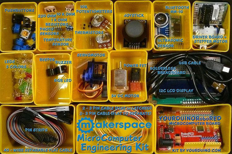
Kit Contents LISTS
Here is the list of all the parts in the kits from Yourduino. For some schools parts were added to the standard kit. They are marked "ADD" on the left side. The kits are like the large photo above PLUS those "ADD" parts.
Media:KitNumbersOriginal-Added.pdf
HOW Do These Things Work TOGETHER ? ?
Here is how we will THINK about Arduino. There are three main things that are part of all automatic systems:
[Sensor Inputs | Software Decisions | Action Outputs]
All automatic systems, from a simple thermostat to the Mars Rover have those 3 parts.
When you create a new project, YOU will decide the three things:
- WHAT Sensors and Inputs you will CONNECT to Arduino, and on What Pins
- WHAT Software Decisions you will make as you write CODE
- WHAT Output Action Devices will you connect to Arduino, and on What Pins
Sensor Inputs:
These can be simple like a pushbutton switch or complex like a GPS receiver or an accelerometer. There are hundreds of possibilities for sensing things in the Physical World.<br
Action Outputs:
These can be simple like an LED or complex like the motors and motion control of a Robot.
Software Decisions:
This is where you decide what Sensor Inputs Arduino will look at, what Decisions it will make , and what Action Outputs it will cause to happen. You will decide how your project Behaves by how you make decisions in software. You make this actually work by writing software code statements. The software should be organized so these 3 things happen over and over again in Loop:
- READ SENSORS
- MAKE DECISIONS
- TAKE ACTIONS
There are two different types of Inputs and Outputs and you need to understand the difference:
DIGITAL INPUTS and OUTPUTS
'DIGITAL things are BITS that have only two possible values: 0 or 1. Like "The light is OFF or ON"
ANALOG INPUTS and OUTPUTS
'ANALOG things are VALUES that have a Range of Values. Like "The light is BRIGHTER or DIMMER or in between.
The STRUCTURE of an ARDUINO SYSTEM
Let's take a look at this diagram that shows the structure or "architecture" of a microcomputer based system like Arduino.
This shows examples of the kinds of Digital Input devices you might use. And Digital Output devices.
It also shows examples of Analog Input devices and 'Analog Output devices.
AND it shows examples of devices that communicate with SIGNALS that are a sequence of Digital Ones and Zeros. They communicate Data with those signals.

OK, now You go ahead and control A Digital Output (an LED) with software you write.
SOFTWARE TIME - CREATING MIXLY SKETCHES
INSTALL the "MIXLY" software on your computer: MIXLY-INSTALLATION
It'll be a crazy but wonderful time!

Start the MIXLY software on your computer. Let's take a little while to get used to creating MIXLY sketches by dragging functions out from the BLOCKS library on the left. Then we'll come back and start connecting your GIS-MakerSpaceElectronicsCourse kit parts and making more interesting things. We will give you MIXLY examples for each of the devices in the kit.
LOOK AT THE MIXLY MAIN SCREEN

Slow Down! Look at all the parts of the screen. Soon you'll be used to it and get a lot of stuff done.
- The LEFT SECTION: "BLOCKS" has many things you can pull out onto the main screen. The example shows 4 blocks that have been pulled out, and clicked together.
- The CENTER SECTION is where you place your blocks. You also type in or select choices or numbers in the blocks
- UPPER RIGHT selects Language. It may start in Chinese and you'll have to set it to your language
Here is another view of the MIXLY screen. We will use these marked things later:

- BOTTOM CENTER: (Red marked) Things you MUST set up to have things work.
- FIRST, YOU MUST SET THE CORRECT BOARD TYPE AND SERIAL PORT
- "Arduino/Genuino UNO" is correct for us
- The entry "COM3" in the example will be different. On the PC There will usually be only one choice. But you may have COM1 and then some higher number which is Arduino.
- On the MAC, pick the entry that has "tty" in it.
- BOTTOM CENTER also has two buttons:
- "Compile" Checks all the BLOCKS you set up in your code. It might cause error messages that would be found in the LOWER SCREEN SECTION
- You will see a LOT of lines roll by in the LOWER SCREEN SECTION. LOTS of Tekkie stuff you fortunately don't need to worry about!
- "Upload" does both "Compile" and if no errors it creates your Arduino code and UPLOADS it into the RoboRED board, and makes it run.
- "Compile" Checks all the BLOCKS you set up in your code. It might cause error messages that would be found in the LOWER SCREEN SECTION
- FIRST, YOU MUST SET THE CORRECT BOARD TYPE AND SERIAL PORT
After UPLOAD your actual code will start running in the RoboRED or UNO board! In the example, the Pin 13 LED will go HIGH for one second, Then LOW for 1 second. This is called "BLINK!" Next, we'll show you how to DO that!
YOUR FIRST MIXLY ARDUINO SKETCH:
The visible-to-You part of an Arduino software program is called a SKETCH. But the Sketch becomes alive when you upload it to your Arduino. Let's walk through Editing a MIXLY Sketch and Verifying it and Uploading it:
OK, Looking at YOUR MIXLY screen: In the BLOCKS section, click IN/OUT. Should see:

NEXT: Click on the "DigitalWrite" block, HOLD and DRAG it to the right out onto your screen. Should see:

THAT is the way you will find and drag out MIXLY Blocks to use them in your sketches!
BREAK: MIXLY MESS AROUND
Let's get back to your own Software!
Mess around with clicking on BLOCKS sections, and dragging stuff out.
How do you get RID of a block you pulled out? GRAB it with your MOUSE and THROW IT OVER YOUR LEFT SHOULDER! OR click "NEW" in the center tool bar. And there is a TRASH CAN on the lower right too.
FIRST REAL MIXLY SKETCH
NOW: Let's try to do something real. Clear the screen with "NEW" and drag out a "DigitalWrite" block.
NOTICE that there are two SETTINGS you can change: PIN# and Stat. Click PIN# and set it to 13. Leave Stat as HIGH.
DUPLICATE the Block; RIGHT-CLICK and pick DUPLICATE. Drag that block down to make some room. (NOTE: The best place to grab a block is on the little bump on its lower left). On the bottom block change HIGH to LOW.Like this:

NOW get a different block:Click on Control and find and drag out a DELAY block.

Make sure it's separate.Then Duplicate it.
Finally, drag the blocks until they 'click' together like this:

Now LET'S TRY IT OUT!
In the center tool bar, click "Compile". WAIT.. The first time you do this it will take a long time. LOTS of TekkieStuff rolling by in the bottom window. Should eventually say "Compile success!".. Later this will take less than 30 seconds.
HARDWARE TIME!
Get your RoboRED or other Arduino and it's USB Cable. Plug them in. At least one LED should light up on the board. It MIGHT blink another LED.
Before you plug in an Arduino the center bar will look like this: ![]() When you plug in, it should show a number like "COM3" or similar. If there are more than one, pick the highest number. Should look like this:
When you plug in, it should show a number like "COM3" or similar. If there are more than one, pick the highest number. Should look like this:
![]()
WHAT ARE WE REALLY DOING, HERE?? We are making a computer (The RoboRED or Arduino UNO or other) DO what we TELL it to do.
Later you will be hooking up many other parts, like LEDs and Servomotors and controlling them. For now, we will start by using one LED that is already connected on the Arduino board.
The PIN 13 LED: Every Arduino has one LED permanently connected to PIN 13, and we will use that to get started. And soon we will talk about PINS, BITS, VOLTAGE, HIGH, LOW and ALL THAT.
OK,DO IT! Click on Upload. Watch the stuff roll by as it does Compile, and THEN you should see "Upload Success!"
AND the LED on your Arduino board should blink ON 1 second, OFF 1 second..
WHAT'S REALLY HAPPENING??
Your sketch controls that LED with the "DigitalWrite" block.
THIS turns the LED ON:

and THIS turns it off:

The SKETCH you created DID things. Check it out. Look at the 4 blocks and what they do:
- Turn Pin 13 LED ON (HIGH)
- Delay 1000 Milliseconds (1000/1000ths of a second = 1 second) WATCH the LED being ON
- Turn Pin 13 LED OFF (LOW)
- Delay 1000 Milliseconds (1000/1000ths of a second = 1 second) WATCH the LED being OFF
And LOOP (Do that over and over forever, or until you turn it all off).
OK. Mess with it and see what happens: Change the first "Delay" to 100. Upload. Do you see a short blink??
Change it to 10, then 1 and Upload (Cover the LED with your hand to shade it). Can you see 1/1000 of a second blink?? If you had a BRIGHT LED you could make a strobe light. We'll try some other things in a minute.
UnderConstruction SECTION 4/15/25 (OUTLINE below)
'NEXT: Use Arduino as a VOLTMETER and learn Voltage Dividers
OK, its time to continue learning about Voltage,Current, Resistance and All That. You will need that to be able to build interesting projects.
If you have a multimeter / Voltmeter device you can use it also.
You need a VOLTMETER so you can actually sample the invisible Voltage at different parts of circuits. Soon you will be writing your own sketches but here's a sketch you can use to make Arduino into a 2-channel Voltmeter:
Here's what it looks like: There are Two Analog inputs that can read a range of voltages. One is connected to +5V and the other is connected to the center of a two-resistor Voltage Divider. (You'll hear more about Those!).

Here is a pre-written Arduino Sketch that we will use:

The .MIX file is HERE
NOTE: To download .mix files, RIGHT click and "Save Link As"
CONNECTING to Arduino
OK. let's CONNECT some stuff with WIRES, so we can really understand what is going on.
We will use things like this from the Kit to get started:
- BREADBOARD: A prototyping tool used to build temporary circuits without soldering
- diagrams (Samples?)
- First connections: +5v , Gnd.
- Measure with Multimeter if available
- Breadboard: Bond top to bottom Voltage and ground rails??
- Example: Resistor and LED To 5V and to Ground.
- THEN Mixly and Blink
- Then external Resistor/led
ANALOG SENSORS
Voltage Dividers:

Now let's figure out this Voltage Divider stuff. Look at the diagram above. A Voltage Divider has 2 resistors connected in Series, connected to a source of (V)oltage and a (G)round or common point. The connection in the middle between the two resistors is the (S)ignal Output, and is some fraction of the Input Voltage. So we can connect a pot used as a Voltage Divider into the breadboard and connect it with wires.. As we move the pot, the output voltage going to Yourduino varies from 0 to 5 Volts and all the values in between. The way Arduino works gives values from 0 to 1023.
Here are some different potentiometers:

Some potentiometers have a knob you rotate like a volume control. Some have a straight sliding movement. And there are Joysticks which have two potentiometers which change with the handle position.
Let's look "inside" some potentiometers.


One is a "rotary" type and the other is a "slide" type. In both cases, inside there is a Resistive Strip of some material like carbon. The two ends of the strip connect to (V)oltage and (G)nd. The Wiper is moved along the strip when you move the knob on the pot. So you can change the voltage divider action, and send different voltages out the Wiper to an Arduino Analog Input. Arduino can read and report that Voltage, and tell where you moved the knob to. So your human movement becomes a value known to Arduino.
For a LOT more about "Pots", see "The Secret Life of Pots" by R.G. Keen HERE
Analog SENSORS that change their resistance
If we have a photoresistor (Light-dependent Resistor) connected in series with a resistor, we have a voltage divider that changes with the light intensity, giving us a varying voltage. If we have a Thermistor (Temperature-dependent resistor) we have a voltage divider that changes with temperature.
What if you want to measure voltages that are more than 5 volts? You use a Voltage Divider to reduce the voltage. If you make a 3 to 1 ratio voltage divider (say, 20K for the top section and 10K for the bottom), then you can read voltages from 0 to 15 volts. Good for automotive batteries. You could to this by putting two of your 10K resistors in series for the top resistor.
Several Useful Voltage Dividers
Here are several ways "Voltage Dividers" are used with Arduino: (Better Graphic Coming!!)

Those examples (one at a time!) are:
(A) equal voltage divider. The voltage is Half of applied voltage. We use +5V so that mid point will be 2.50 V
(B) three equal resistors. Voltages are 1/3 5V and 2/3 5V
(C) Potentiometer: continuously variable voltage output 0..5V
(D) Same as A but a light dependent resistor AKA Photocell is the top resistor. In dark, voltage out is almost zero. In sunlight it would be almost 5V . So: Increasing voltage out with increasing light. In Mixly, the value could be compared to a constant and then action could be alarm etc.
(E) Same as A but top resistor is temperature dependent "Thermistor". Lower resistance with higher temperature.
The Light Dependent resistor and the thermistor are both rated as 10K ohms at a standard condition. Its 25C for the Thermistor. I forget the standard for the light.
Using a Multimeter to measure voltages (Optional: can go directly to Arduino/Mixly reading voltages)
Get a multimeter and use it to see if we understand this Voltage Stuff. Strip two separate wires off the Rainbow cable. BR (Brown) and RD (Red) would be good. Cut off the connectors at one end. STRIP about 1 to 2 inches of insulation off the cut end. Wind the RD wire tightly around the Positive (+) lead from the multimeter. Use some tape (like used on paper) around it to make it stay in place. Do the same for the BR or other wire.
Connect your actual Arduino with a USB cable to your computer. One red LED should light up. Another LED might be blinking. Learn how to set the multimeter to read "DC Voltage". Then connect the minus (-) lead (BR or whatever you used) to ANY of the pins in a BL (Blue) row. Connect the plus (+) lead (RD or whatever you used) to ANY pin in the RD (Red) row.
What does the meter read?? SHOULD be close to but not exactly 5.0 V. Connect the (+) lead to any of the Ground,(Blue) pins. It should read almost 0.0V
JOYSTICK = 2 Potentiometers and 1 Switch
Now that we see how potentiometers act as voltage dividers, let's look at the Joystick which is really two potentiometers connected to a handle.
DIGITAL SENSORS AND DIGITAL ACTUATORS
Now we will go beyond "Digital Binary" devices that are only ON or OFF.
Many complex and useful devices do much more than turn ON or OFF or DIM. One way they can do this is by sending a longer pattern of On and Off, 1s and 0s, that convey information (such as temperature values). This pattern is a called a Digital Signal
Understanding these digital signals is like knowing a foreign language. We use the word "protocol" to describe a digital language. Like a foreign language, you need a translator to understand each digital protocol. But! Don't worry. Lots of people, all over the world, use Arduino, and they have written translators for Arduino to understand all kinds of digital protocols, for all kinds of devices. Just like you can find a foreign language dictionary at your local library, these protocol translators are in libraries too. These are "libraries" of software that the Arduino team or other people have written for us to use, and are already installed into MIXLY. When we figure out how to do something cool, or how to understand a new digital protocol, we might put our code in a Library and share it with others.
DIGITAL SENSORS
Pushbutton
Let's start with the simplest kind of sensor: a Pushbutton. YOU push the button, it puts out a 1 or a 0 . You connect it to an Arduino Input pin.
We already know how to turn the Pin13 LED on, right?? OK here's a pushbutton wired to the Arduino:

Use a 3-pin cable to connect the switch to Arduino Pin 2. Then start Mixly.
Drag out a Digital Write block so you can control the LED
Drag out a Digital Read block so you can see what the Switch is doing.
Hook them together like this:

With Arduino connected by USB, UPLoad that. Try pushing the Button! What happens??
UH-OH The LED is ON before you press the button. And if you press the button the LED goes OFF.. The world is UpsideDown.

REALITY CHECK TIME Look at our Diagram. Look at the SWITCH, the PULLUP RESISTOR and the INPUT.
What is the INPUT connected to when the switch is NOT pressed?
It's pulled UP to a "1" (Also Known As HIGH AKA +5V) so the LED is turned on. When it's pressed, INPUT is connected to (GROUND AKA "0" AKA "LOW").
Get used to thinking about Arduino DATA as "1" or "HIGH" or "+5V". OR "0" or "LOW" or "GROUND".
IT's EASY TO FIX! LET's DO IT.
Think about this LOGICically. Like what is True or False. In Mixly click on Logic on the left. Drag out a "NOT" . Also drag the "Digital Read" off the "Digital Write". Connect the NOT before the Digital Read. Like this:

Then move the Not Digital Read back to the Digital Write. Like this:

Now UPload that. How does it work now?? You can always FIX any data that is UpSideDown.
BUZZER

Now that you can make the LED come on when you push the button, let's also make a noise when you push it. Look in the Kit for "Buzzer Beeper". They are small round black parts. See the photo to tell them apart. You want the BUZZER. Note that one connection is marked (+). See INFO HERE
Get the multicolored RIBBON CABLE out of the Kit. SEE INFO HERE NOTE: one side starts with BRown-ReD-ORange. Grab BR and RD close to the end and strip them off together separate from the rest. Now you have a "Cable".

Here you can see the small black BUZZER. Note the (+) pin and push the RD wire from your cable onto it. Push the BR wire on the other pin. Then connect the RD-BR cable connected to Arduino. BR to Pin13 Blue (Ground) and RD to Pin13 Yellow (Signal)
Analog: Potentiometer sets blink/beep delay

 Here is a Potentiometer on a breadboard we used for this example:
This example reads the value of a Potentiometer (like a volume control) and displays the value on the Serial Monitor. It also sets the delay in blinking the Pin13 LED.
Here's a Mixly sketch that does that.
Photo (light) Sensor Brick

This is a sensor that reacts to the light level by changing it's resistance. Often called a PhotoResistor. Here's what one looks like on a small circuit board with 3-pin connector.

Here's a Mixly sketch that reads the value from the PhotoResistor with an Arduino Analog Input. The value is displayed on the Serial Monitor. The light level is compared to a (changeable) threshold light level and if it is now darker than the threshold the Pin13 LED is turned on. You could use this to operate a relay to turn on lights, as an example.
Richt-Click and "SaveAs" to download the .Mix file. PhotoresistorValues-LED-OnDark.mix
Ultrasonic Distance Sensor
This is a more complex sensor but it's not hard to use. It has a complex chip on it to do most of the work.


Small low-cost ultrasonic distance measurement modules like this: HC-SR04 are an effective way to sense the presence of nearby objects and the distance to them. Often Robots use these to sense objects or collisions and take appropriate action.
Here's how these modules work: They have two transducers, basically a speaker and a microphone. Ultrasound is a high frequency sound (typically 40 KHz is used). A short burst of sound waves (often only 8 cycles) is sent out the "Transmit" transducer (left, above). Then the "Receive" transducer listens for an echo. So, the principle of ultrasonic distance measurement is the same as with Radio-based radar.
Distance is calculated as: L = C × T/2 , where L is the length, C is the speed of sound in air, T is the time difference from the transmission from the transmitter to the receiver. This is divided by 2 for the two-directions the sound travels. Speed of sound is about: C = 344m / s (20 degrees C room temperature). Speed of sound in air velocity is affected by the air density, and for high accuracy the temperature must be taken into account, either within the module electronics (In the SRF-06 module we have) or in the Arduino software.
Understanding the Science Behind the Ultrasonic Distance Sensor
We have a educational page HERE with much more information about Ultrasonics and Echo Location. It includes a link to a slide show suitable for use in the classroom.
Ultrasonic Module Connections

The module in our example has 4 pins:
- Vcc Operating voltage: 5.0V
- Trig the transmit signal pin
- Echo the received echo pin
- Gnd Ground
Now, we will use MIXLY to write Arduino Software to operate the Ultrasonic Sensor:
Using MIXLY to "Design" the Sketch
Mixly is a visual programming tool used to generate code which is then transferred/uploaded to the Arduino. The following steps are taken to program the Arduino using MIXLY in order to measure distance with the ultrasonic sensor:
- Launch the Mixly.exe application and ensure sure your Arduino is connected to the computer.
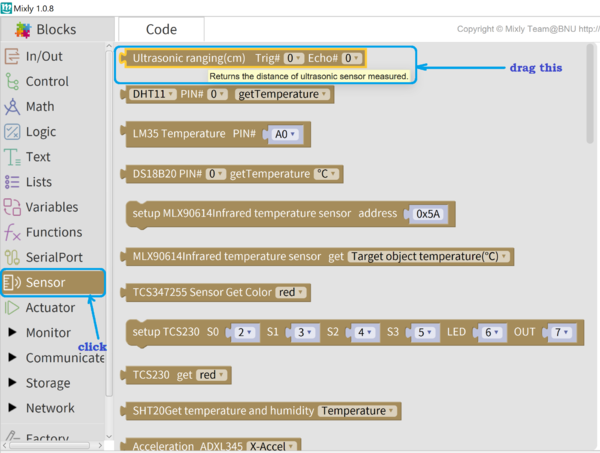
- In the blocks section, click Sensor and drag the ultrasonic sensor block unto the code edit canvas
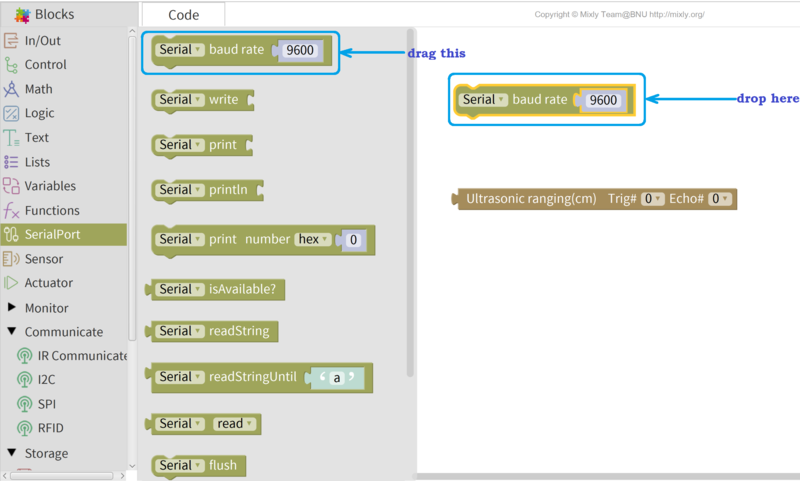
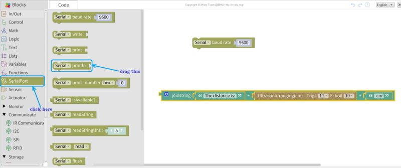
- Add the serial monitor to view the distance. Click on SerialPort and drag the serial baudrate block unto the canvas. This block initializes the serial monitor and sets the baudrate (which is is the speed of serial transmission) to the selected number (e.g. 9600).
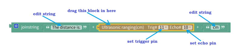
- We are going to use a Text block to create a string which we would use to display the distance on the serial monitor. This text "The distance is: ", the ultrasonic distance measure, and cm, all joined together. In programming, the word for joining things together is concatenation. Click on Text and drag the joinstring block to the canvas.


- Next, drag out the middle block out since we're not going to be needing it and replace that with the ultrasonic sensor block. Click on the other two blocks and edit the strings to the desired text as shown in the image:
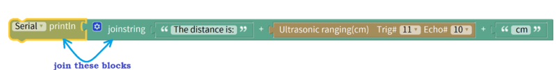
- Add the Serial println block from the SerialPort section. This block would be used to print our desired string to the serial monitor later.
- Join the Serial println block to the joinstring block.
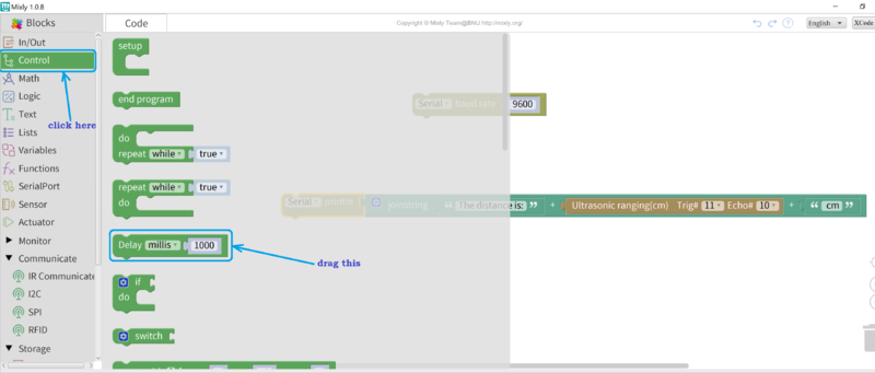
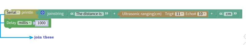
- Next, we're going to add a delay so that we have some time to observe the values printed out on the serial monitor. From the Control block section, drag the Delay millis block. This causes a delay in milliseconds. 1 millisecond = 0.001 second; 1000 milliseconds = 1 second.
- Join the Delay millis block to the other Serial println block, so that after printing the distance value, the process would delay for about 1 second before printing another value.
- Our code is ready. You need to confirm at this point that the Arduino is connected and the proper board and port are selected. In order to generate the code and upload it to the Arduino, click the Upload button and wait till you see Upload success! in the message prompt at the left hand bottom corner.
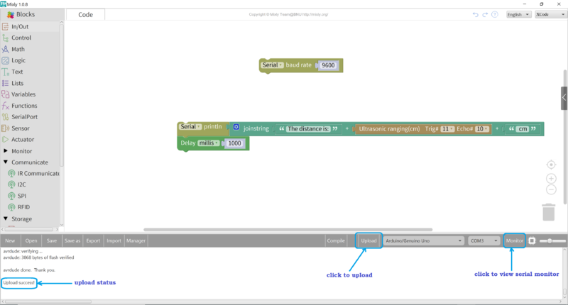
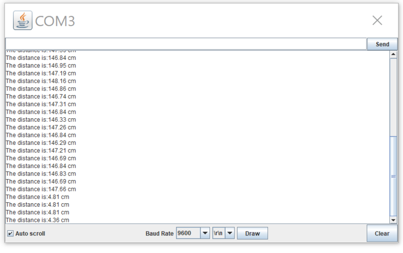
- Finally, click Monitor to reveal the Serial monitor in order to see your displayed information(distance string). The image below shows my own values:


DETECTING OBJECTS WITH ULTRASOUND
Move some flat object like a book in front of the sensor and move it in and out to see the changing distance.
Different objects will reflect a different amount of the Ultrasonic wave, so results will vary a lot. Here are a few examples:
1 ball-point pen, 200mm
2 Hand, 400mm
3.1mm thick plastic sleeve with a wire, 30mm
4. Vernier caliper, 450mm
5. The body (wearing thick clothes), 400mm
6. Wall, 1200mm
7. 1mm thickness soft cotton: undetectable
8. bamboo toothpick, 40mm
9. Stationary Cat ???
Questions or comments welcome
Regards, Terry King
terry@yourduino.com
DIGITAL ACTUATORS
ServoMotor

Many complex and useful devices do much more than turn ON or OFF or DIM. One way they can do this is by sending a longer pattern of ons and offs, 1s and 0s, that convey information (such as temperature values). This pattern is a called a Digital Signal.
Understanding these digital signals is like knowing a foreign language. We use the word "protocol" to describe a digital language. Like a foreign language, you need a translator to understand each digital protocol. But! Don't worry. Lots of people, all over the world, use Arduino, and they have written translators for Arduino to understand all kinds of digital protocols, for all kinds of devices. Just like you can find a foreign language dictionary at your local library, these protocol translators are in libraries too. These are "libraries" of software that the Arduino team or other people have written for us to use, and are already installed into MIXLY. When we figure out how to do something cool, or how to understand a new digital protocol, we might put our code in a Library and share it with others.
Next we are going to use a library to let the Arduino understand how to talk to a Servo Motor.
(A Signal Output): Standard servos like the one in the Kit are controlled by ON-OFF signal pulses sent to them. They rotate their output shaft to a position you command them to go to. You can connect your servo directly to a 3-pin connector on the RoboRED.
Standard Servo Motors (Servo for short) like the one in the Kit were originally made to steer radio controlled airplanes. They rotate the lever on top to the position that you command. To talk to a Servo, Arduino has to send the right pattern of On and Off, the right protocol. There is a library to translate the position you want to the Servo's protocol so it will understand and work correctly. This gives the Arduino a new kind of Output, that can move things on command. The library that the Arduino needs to talk to the Servo is all ready to go in MIXLY. In MIXLY, libraries make a new kind of block, that does this new thing. To use the Servo, go to the Blocks list, in the Actuator section find the block that looks like this..

Let's use the Servo block to control the Servo. For these examples, connect your servo to Pin 9 on the YourDuino 3-pin connector, like this:

In MIXLY, Fill in the PIN# on the Servo block to tell the block where the Servo is plugged in. Tell the block where to point the Servo by giving it a position in degrees from 0 to 180. Its best not to use the very ends of the Servo range, because the gears can jam. So really, its best to only use from 10 to 170.
And this block knows it takes a while for the Servo to move to the new place. So you can tell the block to wait by giving it a Delay (in milliseconds) to make sure the Servo has time to get to the new place before MIXLY goes to the next block.

Here is an example the just commands the Servo to move back and forth . Here is how it looks in MIXLY.

CHALLENGE: POT CONTROL OF SERVO
Next, lets take an input we know from before, and use it to control the servo.
With your Pot connected to Analog Pin 0 (First Analog pin) you can make the servo follow your pot position.
Remember: The Pot digital value goes from 0..1023 You will need to map that to the servo 0..180 (degrees)
DC motor controller L9110
UNDER CONSTRUCTION 04/22/2025 -----


Here are the parts we will use to test how this all works. There are a L9100 Motor driver board (2 channels for 2 motors), a yellow DC motor, A Joystick and a ribbon cable we will use to connect things. Separate out a 10wire section from a wider cable, from Brown (1) to Black (0)
On the right is the cable layout we will use. Notice that some unused wires are folded back under. The remaining wires are the right (according to Color Code) Numbers for the Arduino pins they will be connected to.

Here are the connections we will make from motor(s) to Arduino. Ribbon cable to Arduino on left, Motor Wires on right.
MIXLY EXAMPLE
Here is a simple example which controls the motor pins 3 and 5. This runs the motor in forward and reverse at at medium speed.

This example shows how to do things that are more complicated but build ability to do many complex things. It creates -----Procedures----- for certain functions.

ARDUINO IDE EXAMPLE
 1 /* YourDuinoStarter Example: Sketch Template
 2  - WHAT IT DOES Tests 1 motor on L9110 motor driver
 3  - SEE the comments after "//" on each line below
 4  - CONNECTIONS:
 5    - L9110: +5v , Gnd, A1A=pin3, A1B=pin5
 6    - Yellow geared motor or Equivalent: L9110 = MotorA
 7
 8
 9  - V1.00 01/30/2025
10    Questions: terry@yourduino.com */
11
12 /*-----( Import needed libraries )-----*/
13 //none
14 /*-----( Declare Constants and Pin Numbers )-----*/
15 // Define L9110 control pins
16 #define  motorIA 3  // Connect to IA on L9110
17 #define  motorIB 5  // Connect to IB on L9110
18 /*-----( Declare objects )-----*/
19 //none
20 /*-----( Declare Variables )-----*/
21 //none
22
23 void setup()   /****** SETUP: RUNS ONCE ******/
24 {
25   // Set motor control pins as outputs
26   pinMode(motorIA, OUTPUT);
27   pinMode(motorIB, OUTPUT);
28 }//--(end setup )---
29
30
31 void loop()   /****** LOOP: RUNS CONSTANTLY ******/
32 {
33   // Rotate motor clockwise
34   analogWrite(motorIA, 255);  // Full speed
35   digitalWrite(motorIB, LOW);
36   delay(1000);
37   // Stop the motor
38   digitalWrite(motorIA, LOW);
39   digitalWrite(motorIB, LOW);
40
41   delay(2000);
42
43   // Rotate motor counterclockwise
44   digitalWrite(motorIA, LOW);
45   analogWrite(motorIB, 255);  // Full speed
46   delay(1000);
47   // Stop the motor
48   digitalWrite(motorIA, LOW);
49   digitalWrite(motorIB, LOW);
50
51   delay(4000);
52
53 }//--(end main loop )---
54
55 /*-----( Declare User-written Functions )-----*/
56 //none
57
58 //*********( THE END )***********
STEPPER MOTORS
ABOUT STEPPER MOTORS:
An excellent page about stepper motors is on the RepRap 3D Printer WIKI here:
A stepper motor is a motor controlled by a number of electromagnets. The center shaft has a series of permanent magnets mounted on it, and the electromagnets surrounding the shaft are alternately given current or not, creating magnetic fields which repulse or attract the magnets on the shaft, causing the motor to rotate.
This design allows for very precise control of the motor: by proper pulsing, it can be turned in very accurate steps of set degree increments (for example, two-degree increments, half-degree increments, etc.). They are used in printers, disk drives, and other devices where precise positioning of the motor is necessary.
Small Stepper Motor and Driver Board
MIXLY sketch below..
NOTE: The connections can be confusing! The code examples below assume you are connecting 4 Arduino pins in sequence to pins IN1,IN2,IN3,IN4 on the motor driver board shown. Then in the stepper library statement the correct sequence of motor pins is taken care of. See photos below.

Example: Arduino Connections
Pins 8,9,10,11 will be connected to In1,In2,In3,In4 Color code sequence: Brown-Red-Orange-Yellow Then Green=Ground, Blue=5V


It's easier to get the connections right if you use colored wires like THESE
|
Arduino Pin |
Driver pin |
Color |
|
8 |
1 |
brown |
|
9 |
2 |
red |
|
10 |
3 |
orange |
|
11 |
4 |
yellow |
|
GND |
- |
green |
|
VCC +5V |
+ |
blue |
Then software is initialized in 1-3-2-4 sequence:
Stepper small_stepper(STEPS, 8, 10, 9, 11); //Example Software Sketch below.
NOTE: If your motor just buzzes or runs incorrectly, the connections are probably wrong.
MIXLY SKETCHES CONTROL STEPPER MOTOR
TO DO: Pot controls stepper speed and direction..
NOTE: The StepsPerRevolution value MUST agree with the physical motor you have. It is 2048 for the small geared stepper we show.
NOTE: The SetSpeed value is in Revolutions Per MINUTE (RPM). These geared-down motors have a MAXimum of 15 RPM.
StepperHalfTurnReverse

Get the .MIX file here: https://www.yourduino.com/docs/MixlyExamples/StepperHalfTurnReverse.mix
StepperOneStepAtATime
This example steps the motor ONE step at a time, very slowly (You can change the delay). This shows the actual action as the software and the motor driver board do a sequence of four bits ON and OFF in the right sequence of the internal electromagnets to turn the motor. NOTICE that two magnets at a time are always turned on, and also that only one magnet is changed at a time for each step.

Get the .MIX file here: https://www.yourduino.com/docs/MixlyExamples/StepperOneStepAtATime.mix
JoystickStepperPosition
This example reads the position of the X axis of a joystick and calculates how many steps clockwise or counterclockwise are needed to position the stepper. The Joystick position is calculated a 0 to 350 degrees. The stepper starts at the Joystick center position which is defined as 180 degrees. As the joystick is moved towards 0 or toward 360 degrees the stepper follows the motion. If the joystick is released to its center position the stepper goes back to the 180 degree position.

Get the .MIX file here: https://www.yourduino.com/docs/MixlyExamples/JoystickToStepperPosition.mix
Here's a look at the way we tried this out...

MOTOR DETAILS
The small stepper motor and driver board in a typical kit is a 5v 28YBJ-48 Stepper Motor with Gear Reduction, so it has good torque for its size, but relatively slow motion. These motors/drivers are made by the millions for A/C units, fans, duct controls etc. which is why they are so inexpensive.
4 Phase 5 Wire Connection

- Phase : 4
- Current : 160 mA per winding (320 mA total in 4-step mode) Measured: 250mA stopped, 200 mA running fast
- Resistance : 31 Ω per coil winding (from Red wire to any coil) (Some 24-28 ohms)
- Voltage : 5V DC
- Step Angle (8-Step sequence: Internal Motor alone): 5.625° (64 steps per revolution)
- Step Angle (4-Step sequence: Internal Motor alone): 11.25° (32 steps per revolution)
- Gear Reduction ratio: 1 / 64 (Not really exact: probably 63.68395.:1 )
- SO: it takes (64*64 = 4096 steps per output shaft revolution.. In 8-step sequence.
- SO: it takes (32*64 = 2048 steps per output shaft revolution.. In 4-step sequence.
- NOTE: Arduino "Stepper Library" runs in 4-step mode
- No-Load Pull-Out Frequency : 800pps
- No-Load Pull-In Frequency : 500pps
- Pull-In Torque : ≥ 78.4mN.m
- Wiring Instruction : A (Blue), B (Pink), C (Yellow), D (Orange), E (Red, Mid-Point)
- Weight : 30g
PROBLEMS?? (Motor Just Vibrates??)
NOTE: If your motor vibrates but does not turn or will only run in one direction, it's wires are probably connected with the wrong sequence.
The Arduino pin connections need to have 4 pins connected to Motor Driver In1, In2, In3, In4 and then the pins entered in the software in the sequence 1-3-2-4 for proper sequencing. Also, The + and - pins near "5-12V" need to be connected:
- - to Arduino Ground,
- + to Arduino +5 (for one motor test only) or (best) to a separate +5V 1A power supply.
A ROBOT EXAMPLE: MotorDriver/Ultrasonic/Servo
Let's talk about Integrating what we've learned to make a small "Robot Car".

This robot will include the main parts we have already learned about:
- The Ultrasonic Distance Sensor
- The ServoMotor (To point the Ultrasonic in multiple directions
- The Motor Driver to separately control the Yellow DC motors and wheels
TO DO: WIRING DIAGRAM
You will see the fairly complex MIXLY code below that moves the robot forward, and then "Looks" (with ultrasonic echo sensor) Left, Right And Ahead for obstacles. The it moves away from the obstacle and resumes running.. But in Mixly you can write named procedures that do specific things, like "Turn Left 90 degrees", and test them. Then in the main loop you use those names, so it looks like this:

Get the .MIX file here: https://www.yourduino.com/docs/MixlyExamples/LookAroundTry4.mix
CONTROLLING HIGHER POWER
Power FET brick

This module can switch DC power (5V to 24V DC) on and off. Current switched can be up to 3 to 5 amps.
Pinout and Connections
 Pin/Terminal   Function
-------------- --------------------------------------------
 SIG            Control signal (from microcontroller)
 VCC            5V logic supply
 GND            Ground (logic and load reference)
 VIN            Input voltage for the load (5–24V typical)
 V+             Positive terminal for the load
 V-             Negative terminal for the load
- The **SIG** pin receives the control signal (PWM or digital HIGH/LOW) from the microcontroller.
- **VCC** and **GND** are connected to the 5V and GND pins of the microcontroller, respectively.
- **VIN** and **GND** (on the screw terminals) are connected to the external power supply for the load.
- The load is connected to **V+** and **V-** (or OUT), which are switched by the MOSFET
Typical Use Cases
- Switching DC loads such as motors, LEDs, pumps, or solenoid valves.
- PWM control for dimming LEDs or adjusting motor speed.
- Allows microcontrollers to safely control higher voltage/current devices.
POWER FET Example: Dimming 12V bulb
We will use the PowerFET module to control and dim a 12V 2 Amp bulb of the MR16 type often used for home lighting. NOTE: We are using an Incandescent version. Newer MR16 LED bulbs are not dimmable but can be switched ON and OFF with the PowerFET module.
Review the PowerFET module connections above. Since we want to use PWM to dim the bulb we must use an arduino pin that supports PWM. We'll use pin 11.
So there are 3 hardware connections we need to make:
- the signal from arduino pin 11 to the PowerFET module: 3 wires or a 3-pin cable with these connections
- GND Ground
- VCC Voltage (+5V)
- SIG Signal
- EXTERNAL Power for the bulb. We will use a 12V 2 amp rated plug-in power supply.
- GND (The Negative connection of the external supply)
- VIN (+12V IN - The positive connection of the external supply)
- The LOAD (The bulb in this case)
- V- (Voltage Minus to the bulb. Incandescent does not matter, but LED bulbs must have correct polarity.
- V+ (Voltage Plus to the bulb)
CONNECTION view

- Notice the 3-pin cable to Arduino pin 11 (and Gnd and +5V Vcc)
- See the POWER connection on the lower right of the module
- See the LOAD (bulb) connection on the lower right of the module
Mixly Example: PWM controlling the bulb Brighter and Dimmer

Note that the PWM values go from 0 to 255 and back to 0
The Arduino C++ Code generated by Mixly, for example

See the C++ mode that Mixly generated to actually program arduino to control the bulb
VIDEO of the bulb being controlled (click the photo) =
Relay boards

Here is a typical relay board with two identical relays. A Relay is a SWITCH that is flipped by a small electromagnet inside the case of the relay.
How Relay Contacts Work:

Look at the photo of a relay on the left. Notice the 3 screw-type terminals. They are labelled "NO", "COM", "NC". Those labels mean:
- NO: Normally Open
- COM: Common Connection
- NC: Normally Closed
Look at the diagram on the right. This shows the switch that is inside the relay. This switch is "thrown" by the electromagnet inside. The diagram shows that COM is connected to the Normally Closed contact. That's the case when the relay is off. When the relay is turned on the electromagnet flips the switch up and COM is then connected to Normally Open. So, if we want a lamp to be on when the relay is on, we connect our circuit from COM to NO.
Relay Board How-To and Examples
Optical Isolation
"Optically Isolated" means an "Opto-isolator" chip is used to isolate the relay from the Arduino. See: http://en.wikipedia.org/wiki/Optoisolator So only a beam of Infrared light (The little blue arrows in the diagram below) connects the Arduino circuitry to the relay and switching parts. Here's what an opto-isolated board looks like, followed by it's circuit diagram:

Optoisolation / Crydoms
COMMUNICATIONS SYSTEMS
- wired systems
- wireless systems: Bluetooth and WiFi