GIS-PythonElectronicsWithArduino
HOW-TO for the GISElectronics YourDuino Workshop Kit and PYTHON
We are developing and testing this in cooperation with the Georgetown International School in Guyana, South America. But it will be made available for everyone soon.
We will be using two different ways of connecting Arduino to the real world outside the browser.
NOT COMPLETE DO NOT USE YET
What is Physical Computing ?
Using a computer to SENSE real things like temperature or light and using the computer to CONTROL real things like lights and motors is called PHYSICAL COMPUTING.
- One way to do this is to write code using the Arduino IDE system and upload it directly to an Arduino. This code is written in an easy version of C and C++ that is specific to Arduino.
- A second way is to write your code in a higher level language like python on a larger computer and use it to communicate with an Arduino with some Protocol. We will use a protocol and system called TeleMetrix.
How to use Python with Arduino
In the past you may have coded something like the "Blink" sketch and uploaded it to an Arduino board. It blinked an LED on and off. Arduino sketches are written in a language similar to C++ and are compiled and recorded on the flash memory of the microcontroller when you press Upload.
Unfortunately, it is not possible to directly run Python code on most Arduino boards like the Arduino UNO or our RoboRED. Here are the key points to understand:
- Arduino boards like UNO use microcontrollers with limited memory and processing power that are not capable of running a full Python interpreter.
- Arduino boards are programmed using C++ in the Arduino IDE, not Python.
However, you can write Python code on your computer to communicate with and control an Arduino board over the serial connection. This allows you to write the main program logic and user interaction in Python while using the Arduino for hardware interfacing to Sensors and Actuators.
We will use a Python library called Telemetrix to send commands from Python on a computer to an Arduino.
Fortunately, there are standard protocols to do all this! We will use Telemetrix4Arduino. This protocol establishes a serial communication format with Arduino that allows you to read digital and analog inputs, as well as send information to digital and analog outputs.
NOTE: We have made all this work on Windows PCs but have not yet tested all the features on Apple/MAC computers. There will be specific how-to sections for MAC later.
Installing Python, Telemetrix, Arduino IDE and TeleMetrix4Arduino
There are four steps to getting all this installed and working. Each of these is a separate page that can be used independently. You should go to each page by the links below, and then come back here to continue.
- Install standard python3 on your PC or MAC
- install the TeleMetrix library on your PC or MAC to allow python programs to communicate with your Arduino
- the Arduino IDE system on your PC or MAC
- install the TeleMetrix4Arduino 'firmware' on your arduino.
When you are done with the last install, we have some example python programs you can try out. The first python example needs only the Arduino and USB cable connected to try to blink the onboard LED. Others need a servo and / or a potentiometer from the kit. Link is HERE
The GIS-PythonElectronicsWithArduino MAKERSPACE WORKSHOP KIT
We will use the kit and the components in it to learn how Arduino works and to explore many of the devices you can use with it.
You will use both the Arduino IDE programming environment and PYTHON with the (TBD - Python IDLE?) editor to write your own code. You will learn how to SENSE things in the Real World and control ACTUATORS to control your own devices.
INTRODUCTION to the KIT
What IS ALL THIS STUFF??
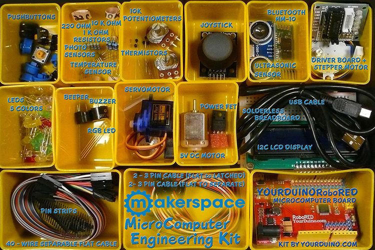
The following pages will show you what each of the components in the kit ARE, and give you code examples in ARDUINO (C++ like), PYTHON and MIXLY (Drag-Drop) Sketch examples for each one. Then you can combine some components to make examples of Automatic Systems such as a lighting controller or a automatic NightLight for your room. Or an automatic CatFood Door ... OR ???
You're probably here because you're interested in MAKING things with Arduino. The first questions:
- What can you do with a MicroComputer like Arduino? See this link and See what THESE HIGH SCHOOL KIDS HAVE DONE!
- How do you get started?
To get started, we think you need 4 things:
- Clear Information
- Practical, Low-Cost hardware to learn with
- Easy-to-use software to make your own code
- Detailed How-To DO IT.
NOW: Making things with Electronics and MicroComputers is different than Woodworking or Metalworking.
There are a couple of little problems:
- AND, Software is INVISIBLE !
NO WORRIES! We will show you the ways to make these powerful tools Visible so you can use them.
START HERE
GETTING STARTED:
Check out the YourDuino RoboRED
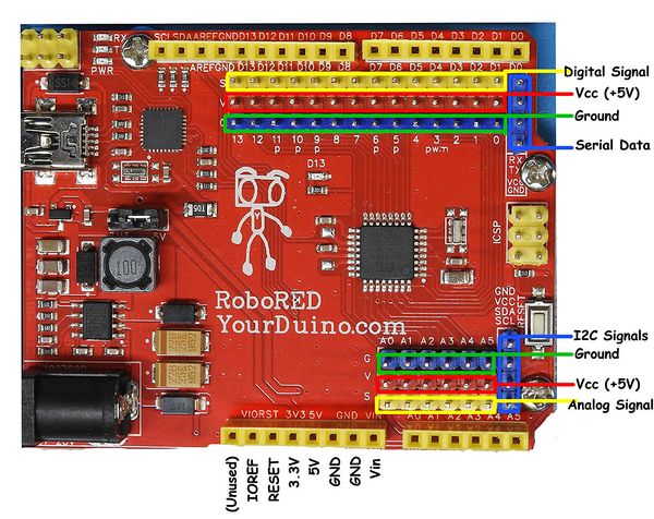
The YourDuino RoboRED is used in your kit. (Yours may have a Black Board but it's the same. ) It is equivalent to an Arduino UNO but has several added features, like easy-to-connect pins on every Input/Output pin. Near the upper left is the PWR LED which should light up whenever the board is plugged into a USB connection, or has power from an external power supply.
At the upper left there are two added red LEDs (RX and TX) which will blink when a software sketch is being downloaded to the board, or other data is being transferred over USB.
In the center is a red LED which is internally connected to pin 13 through a current-limiting resistor. It should blink after you load the example BLINK software sketch. The colored 3-pin connectors on every I/O Pin make it easy to connect many input and output devices. Vcc(+5V) pins and (Ground) pins with every I/O pin are good for connections to breadboards etc.
HOW DOES THIS WORK??
Look at an Ipod or a RoboRED or a CellPhone or some other circuit board. You can't see the electrons moving. All you can see or hear is the Results of electricity.
If you want to make things and get results, you need to know what the electrons are doing. And Why. And How.
And, by the way, SoftWare Is Invisible Too!
You can't see the the code that some people wrote that makes your CellPhone or TV or Ipod work.
Not To Worry! Your kit and the ArduinoInfo.Info website is about making Electronics and Software visible to you, and understandable to you. You can learn how to make Electricity visible, how to trace it, how to measure it, and how to tell what it is doing. And you can learn how to create Software "Sketches" that create new and interesting high-tech things.
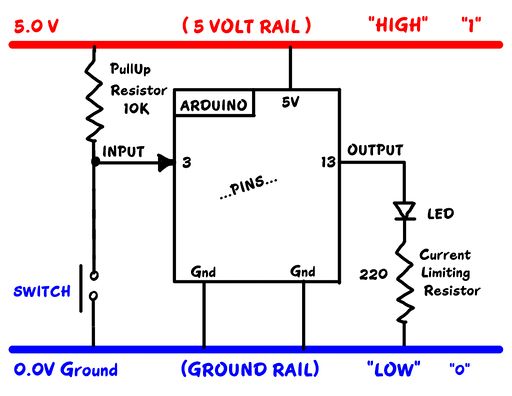
If we understand this stuff, we can start to make many more-interesting things work. Let's THINK about it. We have wires and circuits and electricity. It's easier to think about it if we use some SYMBOLS to make DIAGRAMS. Let's look at This Diagram :
Slow Down Time: Look carefully:
Your RoboRED (Arduino) runs on Electricity. A supply of '5 volts' comes from the USB cable or batteries. At the top and bottom of the diagram there are two main connections:
5 VOLTS
GROUND
Find them on the diagram. What about "RAILS"? A lot of things connect to that 5 Volts and that Ground. Tekkie-Speak calls them 'rails' like railroad rails running through a project or circuit. Let's look at that diagram in detail. NOW, Remember when you tried out the BLINK sketch??
You told Arduino to connect Pin 13 (Find it??) to HIGH (The 5V Rail). It did it. And the LED lit up. What happened when you told it to connect Pin 13 to LOW (Ground?)
Soon you'll hook up a switch like on the diagram. Then lots of other interesting things.
How to connect wires to your Arduino
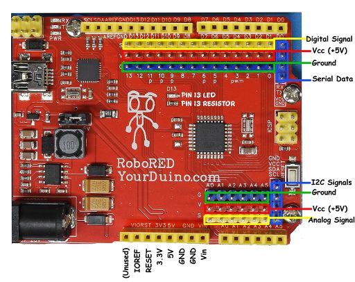
Take a close look at the RoboRED (An Arduino UNO compatible):
See the long sections of RED pin strips labelled "+ 5 V" Those are the +5V Rails.
See the long sections of BLUE pin strips labelled "Ground" Those are the Ground Rails.
You will hook lots of things to those rails.
See the long sections of YELLOW pin strips labelled with Pin Numbers. Each of those connects to a different pin. There are Digital Signals like the pin 13 you used, and Analog Signals you will use soon.
Look Closely Now: See the "Pin 13 LED" and "Pin 13 RESISTOR" marked on the RoboRED. Those are the parts shown on the Diagram, and the actual parts you control with your BLINK Sketch.
All right. You're the Programmer! And as we promised next we'll figure out how to use PYTHON to control your RoboRED.
We'll start hooking up the Electronics Parts in your Kit! And we'll give you example Software Sketches for most of them. And you'll start writing your own Real World PYTHON

